Research Summary Report of C01
Bridging Scales – From Geometric Part Details to Construction Elements
[02.02.2024]
Kollmannsberger, Stefan; stefan.kollmannsberger@tum.de
TUM, Computational Modeling and Simulation
Bürchner, Tim; tim.buerchner@tum.de
TUM, Computational Modeling and Simulation
Rank, Ernst; ernst.rank@tum.de
TUM, Institute for Advanced Study
Digital models for Additive Manufacturing (AM) must consider many different geometric scales. The scales range from micrometers up to tens of meters for metal- or concrete-based processes and mutually influence each other. Project C01 aims to develop consistent geometric and computational descriptions for the relevant AM products on all these scales.
As-built structures naturally deviate from as-designed structures in geometry, topology, and material properties especially in additive manufacturing. The consequences of such deviations upon the structural behaviour are commonly termed the effect of defect. To this end, this project will design a methodology to digitally assess the effect of defect.
Summary
To analyze the effect of defects it is first necessary to identify such defects. This can be carried out via CT scans or other imaging methods, yet also by methods which we bring into the TRR via our previous research on full waveform inversion (FWI). We report here on extensions of the finite cell method (FCM), our main “working horse” in this TRR, to detect flaws within already produced parts using FWI.
FWI employs a data fitting process to iteratively generate a digital twin of the sample in terms of a material model. Figure 1 illustrates the general algorithmic framework employed in FWI. Starting point is an initial model that is not aware of the sub-surface properties of the sample. In the spirit of the finite cell method, this initial geometric model is described by an indicator function α(x). Further, we define a function γ(x) which scales the initially assumed material distribution to zero in regions of detected flaws.
To identify anomalies, waves are then emitted into the model at specific locations of its boundary and recorded at sensor locations. The obtained signals are compared in a suitable norm of difference to wave patterns recorded in virtual or real experiments. We then use gradient-based optimization to minimize the chosen norm with respect to γ(x). After performing several model updates, function γ(x) emerges as a geometric model of the detected flaws.
An example of the result of the process presented in Figure 1 is depicted in Figure 2. Therin, a hidden flaw (the ellipse) is recovered accurately within a complex shaped domain using a multi-scale approach in only 4 iterations.
The methodology was extended to 3D for the shelltonic demonstrator of the TRR into which cavities were introduced artificially to demonstrate the capability of the developed methodology, see Figure 3.
The presented methodology is a cost-efficient alternative to CT scanning and, at the same time, may be used in cases in which CT scans are unfeasible due to the size of the inspected object.
Current State of Research
The detections of flaws as presented in Figure 2 and Figure 3 were carried out using an initial geometric model that describes the as-designed part by means of the indicator function α(x).
However, the as-designed geometry of the part may differ significantly from its as-built geometry. It is, thus, desirable to use the as-built geometry as an initial geometry α(x). Such an as-built initial geometric model can be provided by a regular or oriented point cloud which may be obtained from surface scans as depicted in Figure 4.
The representation of point clouds as a geometric model α(x) is naturally possible within the finite cell method. However, the reconstruction of flaws within models described by oriented point clouds using the framework depicted in Figure 1 is currently under investigation.
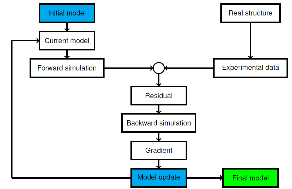
Fig 1: FWI Framework [3].
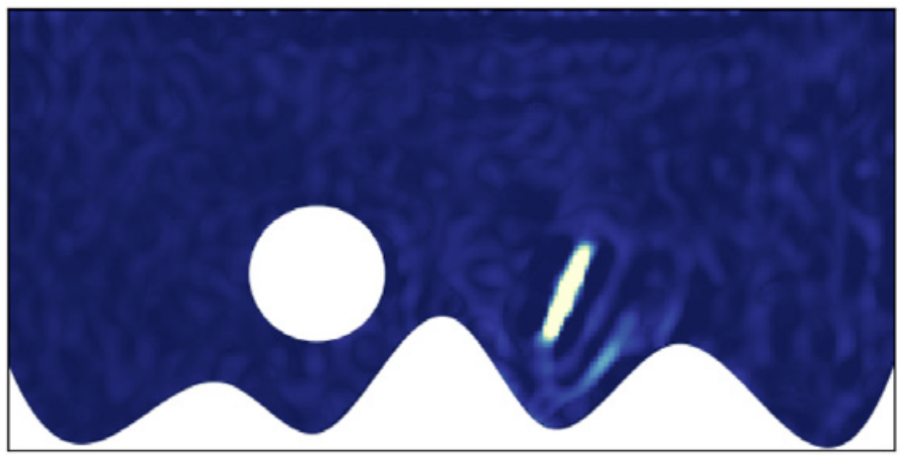
Fig 2: Detection of a flaw (ellipse) in a complex shaped domain (blue) using an extension of the finite cell method for full waveform inversion in [1].
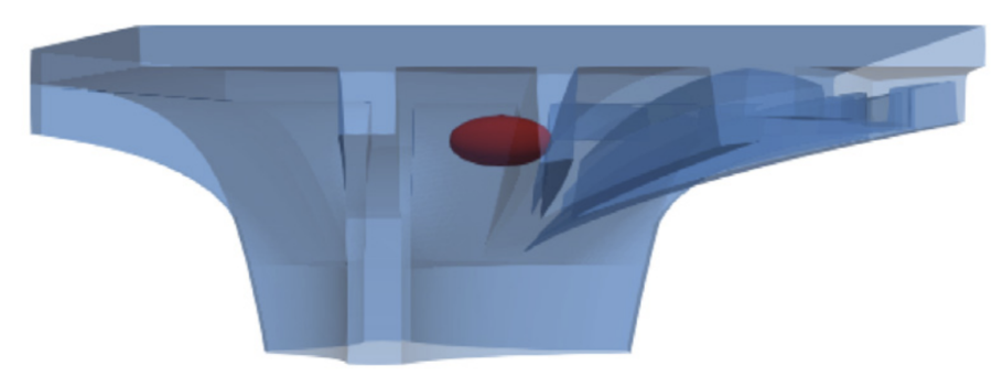
Fig 3: shelltonic demonstrator with introduced flaw in red, reconstructed flaw (right) [1].

Fig 4: regular (left) and oriented (right) point cloud of the shelltonic demonstrator