Research Summary Report of C04
Integrating Digital Design and Additive Manufacturing through BIM-Based Decision Support and Digital Twin Methods
[14.07.2023]
Li, Chao; doctoral researcher, chao1.li@tum.de
Petzold, Frank; PL, petzold@tum.de
Technical University of Munich, TUM School of Engineering and Design, Chair of Architectural Informatics
The application of Additive Manufacturing (AM) technology requires careful consideration of AM methods‘ boundary conditions. Determining suitable AM methods is critical during the early design stages since changes in design are costly when design becomes more mature. To this end, WP1 of sub-project C04 aims to develop a design decision support system (DDSS) that assists architects and engineers in choosing feasible AM methods for BIM-based design. To achieve this, a knowledge base is formalized, which consists of information on different AM methods and design rules. On top of that, the DDSS analyzes building components’ geometric features and functional properties to provide recommendations for suitable AM methods, as well as visualization for design adaptations.
Summary
In our previous work (see Reference), we put efforts into the formalization of AM knowledge base and a prototype leveraging such knowledge in choosing feasible AM method(s). Using Semantic Web technology, AM knowledge has been formalised as ontologies and rules. Further, we demonstrated how AM knowledge in these forms could assist architects in finding optimal AM methods for their design.
Notably, the mainstream BIM authoring tools do not support robot simulations given printing paths, i.e., an interface between BIM-based design and robot manufacturing is missing. To bridge this gap, we developed a robot simulation tool processing the Fabrication Information Model (FIM, C04 WP2) and computing inverse kinematics. Construction planning in this regard, could be integrated into the BIM-based design and manufacturing processes.
Current state of research
Printing systems deployed in AM are usually determined by joint consideration of process parameters and robotic devices, e.g., printing speed and weight of the end effectors. According to the site condition and vendor-dependent operation manuals, auxiliary equipment such as booster frames, linear unit concrete foundations, etc., might also be demanded. Printing systems’ reach range is visualized using parametric “families” (see Fig. 1) with the input of adaptable parameters such as nozzle length and height of the booster frame. Influencing factors for construction planning, e.g., robots’ self-weight, are also accessible from both ontologies and families.
A prototype for robot simulation has been developed (Fig. 2): it parses and renders the FIM model (provided by WP2) which embeds geometric and process information for printing, e.g., speed, layering direction, etc. Targets are set accordingly, and inverse kinematics are computed using efficient geometric methods. The printing system’s position is synchronised with the BIM environment using the same coordinate system – this way, collisions detected in the simulation tool are informed for system relocation or design adaptation.
Video: Robot simulation tool animating the printing process
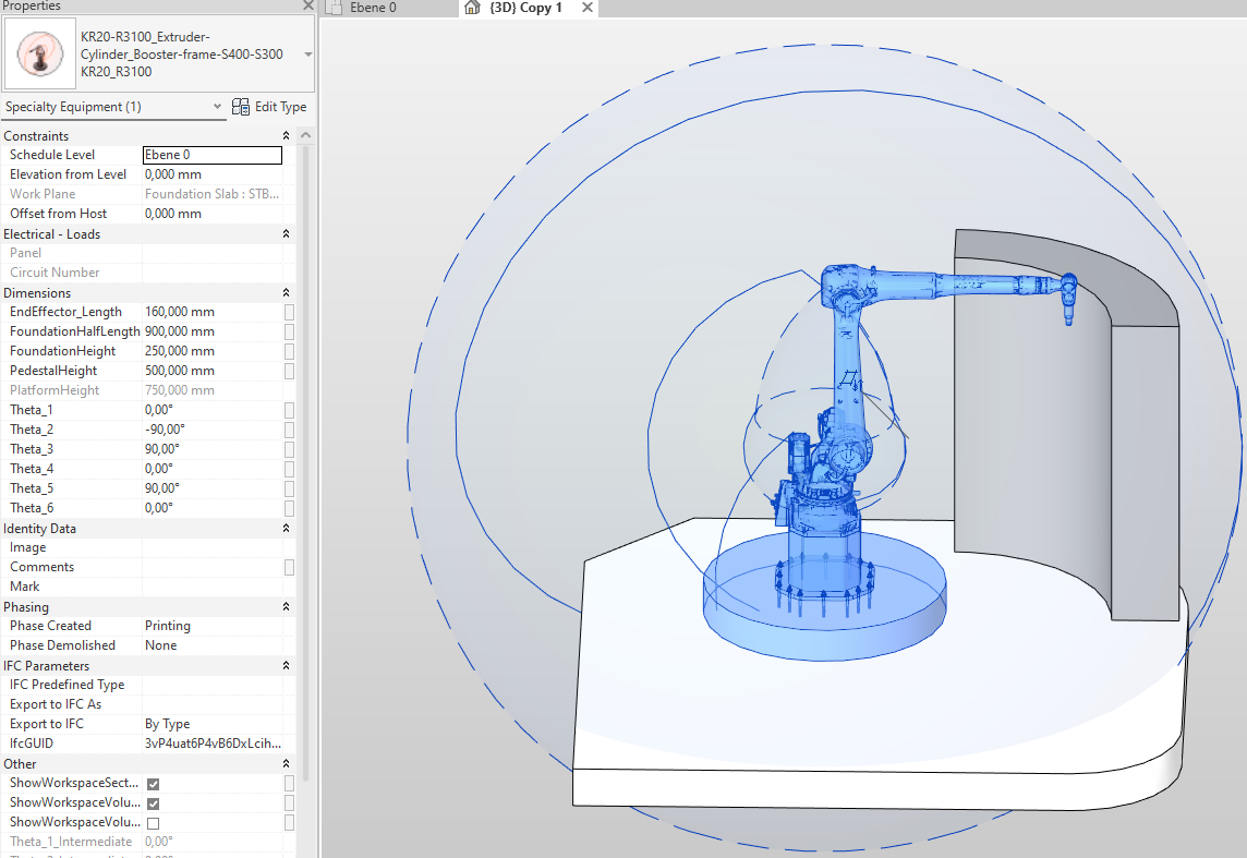
Fig. 1: Parametric robot system using KR3100 / Credit: TUM AI
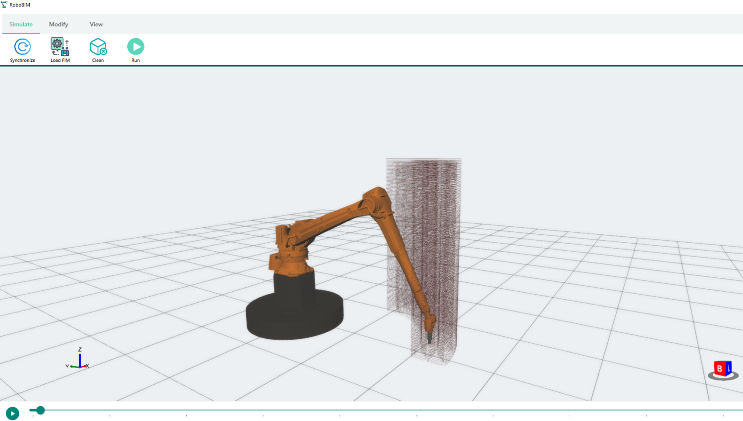
Fig. 2: Robot simulation tool animating the printing process / Credit: TUM AI