Research Summary Report of A07
Wire and Arc Additive Manufacturing (WAAM) of Complex Individualized Steel Components
[26.05.2023]
Müller, Johanna; doctoral researcher, johanna.mueller@mb.tu-chemnitz.de
TU Chemnitz, Institute of Joining and Assembly
The aim of TP A07 is the design, the manufacturing and the testing of complex individualized steel components by means of WAAM. That contains the fundamental investigation of design and the design process for WAAM components. For the manufacturing of steel components by WAAM, stable and reliable processes for basic geometries are qualified and based on that, case study demonstrators for the identification of manufacturing constraints are fabricated. Furthermore, a novel approach for material and component testing is developed to identify local material and component properties.
Summary
The aim of WG Hensel within the TP A07 is to produce large scale steel components by WAAM. For the manufacturing of these components, the general workflow of design, slicing, path planning and printing is used.
Depending on the design of the structure to be fabricated, different slicing strategies can be applied. Fig 1 depicts the two basic approaches. The planar slicing is the simplest way of slicing, but the limitation here is, that it doesn´t take the higher number of layers into account, that is needed in areas with overhangs. In contrast, the equidistant slicing-method is doing so, but for more complex structures that also contain features like undercuts or bridges, this method is numerically not able to slice it.
Within the last reporting period, the slicing methods “equidistantly” and “planar” were in depth investigated and applied to the fabrication of two demonstrators.
The first one is an L-shaped cantilevered part with an overhang of 90°, Fig 2. For this demonstrator, the planar slicing method was applied. In order to realise the overhang as well as closing the thin walled structure in the end, an inclined plane was used to slice this part. Layers were added manually for the overhang areas.
The equidistant slicing was applied to the manufacturing of a Y-Node, compare Fig 3. Here, the dynamically changing overhang was considered by the slicing method.
Current state of research
The inclined slicing method is of interest for structures with a high degree of overhang. Here, the whole CAD-part is inclined and sliced afterwards. The method of inclined slicing offers great advantages for geometrical features like cantilevered structures exhibiting an overhang of 90°. For the depicted L-shaped structure this slicing method is the only way to manufacture without changing the building direction. For the manufacturing, the substrate was tilted 45°. Via that, the overhang was reduced from 90 to 45°.
The Y-node shows an overhang that is dynamically changing in z-direction. Thus, it is a great challenge to slice it planar and to add the additionally needed layers manually. Here, the equidistant approach for slicing is more suitable. It calculates the distance of the layers in the whole structure with regard to the overhang. The limitation of this slicing method is the part in the middle of the node, where the structure closes again (bridge). To realise the manufacturing, the CAD-model was split into two parts: the main body of the node and the bridge. For both the equidistant slicing method was applied.
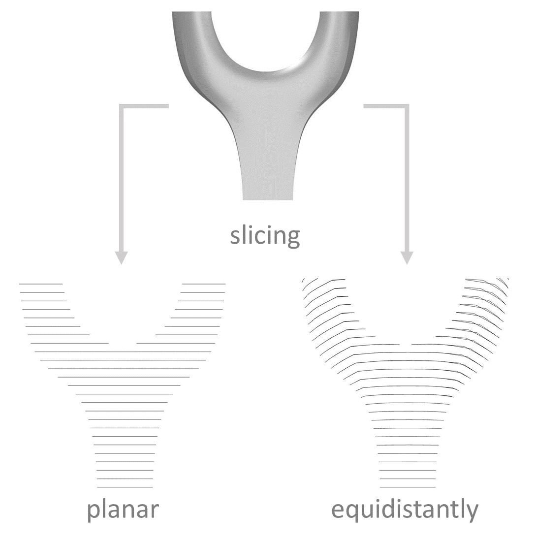
Fig 1: schematic of basic slicing strategies / Credit: A07/ J. Müller
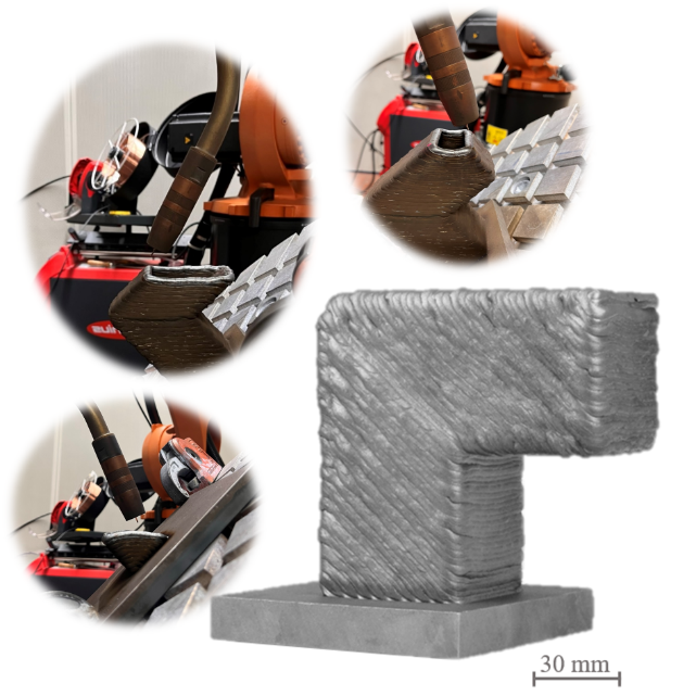
Fig 2: cantilevered demonstrator for the investigation of the inclined slicing with a 45° plane / Credit: A07/ J. Müller
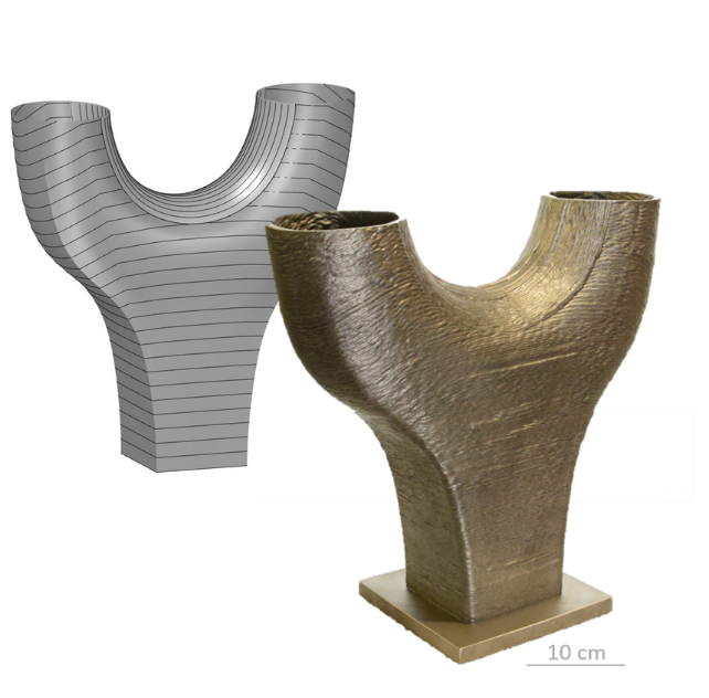
Fig 3: Y-Node produced by WAAM using the equidistant slicing method / Credit: A07/ J. Müller
Y-Node produced by WAAM using the equidistant slicing method