Research Summary Report of C06
Integration of Additive Manufacturing in the Construction Process
[23.12.2022]
Mawas, Karam; Doctoral researcher, k.mawas@tu-braunschweig.de,
Gerke, Markus; Project leader, m.gerke@tu-braunschweig.de,
Maboudi, Mehdi; Associated scientist, m.maboudi@tu-braunschweig.de,
TU Braunschweig, Institute of Geodesy and Photogrammetry (IGP)
Main goal
In order to ensure that a robust process is followed and the printed object adheres faithfully to the designed model, continuous and automatic data capturing and inspection of the process is required. Quality control also ensures that the combination of components into objects can be realized.
Summary
As a result of variations in manufacturing processes, specimens may differ from their as-designed models. Therefore, all manufacturing steps should be equipped with a proper quality control process.
Although quality control of a printed specimen is mainly about capturing the deviation from its designed model, communicating these analyzed controlled results back to the design will close the physical-digital-link and, thus, subsequently updates the digital twin.
While the object is in its rough stage after the initial additive step within 3D shotcreting, i.e., before edge trimming and surface finishing, the printed object quality control takes place to inspect the inlayers (filament extraction). The process can be automated with the help of FIM to enable simultaneous monitoring of changes in the model. For the digital twin concept to be fully automated, the inspected data (inlayers) must be communicated back to the model. Our current research aims to investigate to what extent inlayer extraction is achievable with data captured by TLS (Terrestrial Laser Scanning).
Figure 1 illustrates a simple wall’s design, printing, and quality control stages. Figures 1a and 1b show distinctive layers stacked upon each other (model and after print, respectively). A TLS, mounted on a separate robot, then captures the component’s geometry and position. One of the major outcomes of our previous work is that the data captured by the TLS (“point cloud”) is co-registered to the design-model, that is, the model can directly be compared to the as-is-data. A deviation map is subsequently extracted by employing a Cloud-to-Mesh method (C2M) (see Fig. 1d), which provides a distance for every captured point. For a detailed analysis of the process, it is necessary to use an inlayer segmentation method, which is currently under development. Fig. 1c shows the manual segmentation of the as-printed layers.
Current state of research
Although the printed object component looks similar to its digital model, some details differ. In addition to the intended height not being met, the sides often need to be more accurately printed, and the planned width is often exceeded. Additionally, the segmented point cloud (fig. 2c) shows flaws at the level of individual layers and the total number of layers – 29 instead of 30. Automating the labelling process will make this process much faster and less error-prone while simultaneously extracting the surface of the ‘as-manufactured’ layer. As a result of the extraction of layer surfaces, the digital model could be updated, and advanced FEM analysis could be performed.
For automatic inlayer extraction, the deviation map (Fig. 1d) is translated to an image by generating a grid with the size of the wall by 1mm cell size spacing. Then, the image is processed by nearest neighbour interpolation to ensure a closed representation after grid generation. Lastly, edge detection is carried out on the images to detect the separation lines between the different layers.
The generated image from the point cloud is illustrated in Fig. 2a. The image’s colour information matches the C2M results from the point cloud. Lastly, blue lines resulted from the canny filter to detect the inlayers after converting the image to grey (see Fig. 2b). These are still preliminary results that need further investigation.

Fig. 1: (a) as-designed model, (b) as-printed object, (c) manual inlayer labelling, (d) Cloud-to-Mesh distance in [mm]. Adapted from Slepicka et al. 2022.
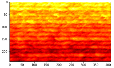
Fig. 2: Patch image with C2M colour information generated from the point cloud of a printed wall. (a) Generated image.
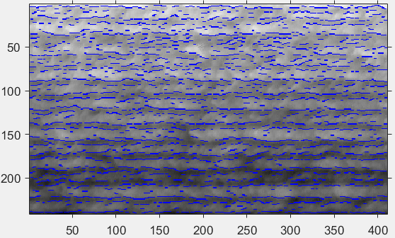
Fig. 2: Patch image with C2M colour information generated from the point cloud of a printed wall. (b) Detected edges in blue.