Research Summary Report of B04
Process Control and Adaptive Path Planning for Additive Manufacturing Processes Based on Industrial Robots with an Extended Degree of Freedom
[11.01.2023]
Ekanayaka, Virama; Doctoral researcher, v.ekanayaka@tu-braunschweig.de,
Hürkamp, André; Project Leader, a.huerkamp@tu-braunschweig.de,
TU Braunschweig, Institute of Machine Tools and Production Technology (IWF)
The integration of robot-guided additive manufacturing in the construction industry increases the degree of automation and can thus lead to an increased productivity and increased component quality. In shotcrete 3D printing (SC3DP), reproducible manufacturing results and ensuring component quality are major challenges, as the properties of shotcrete depend on many different parameters (e.g. temperature, pressure, water-cement ratio, hardening accelerator). The goal of this research project is to develop a reproducible, robot-guided shotcrete process based on multi-model adaptive path planning for the production of large, high-quality and complex components.
Summary
To ensure that the desired geometry is printed, it is essential that an efficient process control is implemented during the SC3DP process. In order to establish the optimal process parameters (nozzle velocity, distance to the printing surface, etc.) to be used during the process, it is required that the material-process interactions are adequately understood. These interaction which subsequently determine the stability of the printed structure as well as its geometry can be investigated through means of simulation.
A novel process based finite element simulation has been developed within the framework of B04, which improves upon the standard practice of utilizing a target CAD geometry. In this approach, the simulated geometry is directly created from the printing trajectory and process parameters as shown in figure 1.
Since the input to the simulation are the process parameters instead of a target CAD geometry, the output of the simulation (deformations, stress, etc.) can be directly correlated to these process parameters, which in turn enables efficient fine-tuning of these parameters to achieve a desired output.
A further challenge when simulating the additive manufacturing process with concrete, is the numerical implementation of the time dependent material properties of concrete. This challenge has been successfully met by encoding a time stamp to each mesh element, which indicates the time at which that element has been printed. The corresponding material properties of that element at each time step in the simulation can then be calculated by simply determining the elapsed time.
Current state of research
The process parameter that was extensively investigated using this simulation approach is the interlayer waiting time. This is a temporal pause between layers to ensure additional hardening time for the underlying layers in order to prevent structural collapse. However, certain constraints must be observed to prevent the forming of cold joints and minimize the printing time.
Figure 2 shows the simulation of the identical structure without interlayer waiting times and with optimally distributed interlayer waiting times.
It can be seen from the simulation results that structural stability could be guaranteed with the correct distribution of interlayer waiting times. This was subsequently verified during printing trials. In the simulations, the Drucker-Prager plasticity model was utilized to capture the behavior of fresh concrete and it could be observed that the onset and progression of plastic deformation, lead to rapid structural collapse.
Furthermore, imperfections arising due to instabilities in the printing process can effectively captured into the simulation (figure 3), by displacing the nodes of the corresponding layer where the irregularity occurred by a specified amount.
A sensitivity analysis of the model parameters with respect to the structural deformation has also been carried out.
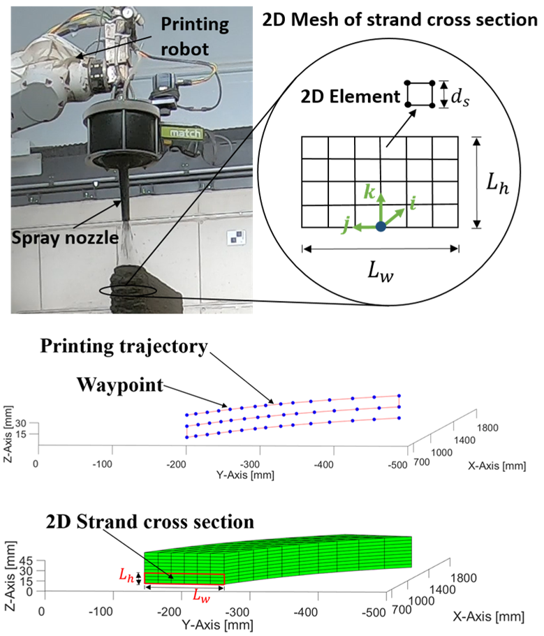
Fig 1: Process-based modelling approach/ Credit: IWF
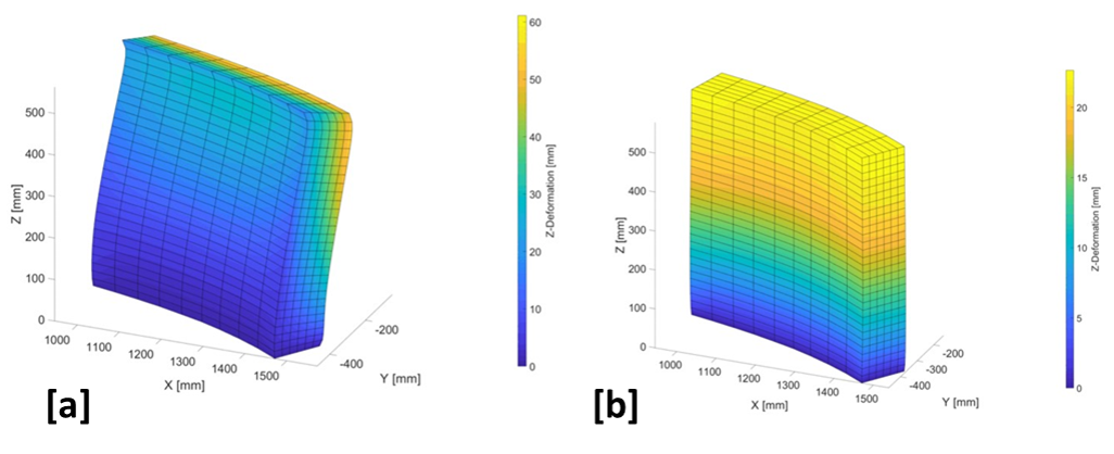
Fig 2: [a] without interlayer waiting times [b] with optimally distributed interlayer waiting times / Credit: IWF
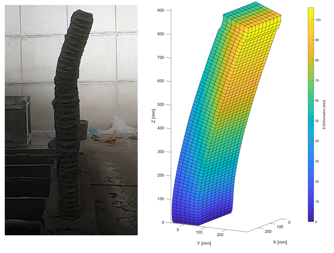
Fig 3: Simulation of the collapse of a straight wall due to a printing imperfection: IWF