Research Summary Report A07
Wire and Arc Additive Manufacturing (WAAM) of complex individualized steel components
[30.09.2022]
Müller, Johanna; doctoral researcher
johanna.mueller@tu-braunschweig.de
TU Braunschweig, Institute of Joining and Welding
Main goal
The aim of TP A07 is the design, the manufacturing and the testing of complex individualized steel components by means of WAAM. That contains the fundamental investigation of design and the design process for WAAM components. For the manufacturing of steel components by WAAM, stable and reliable processes for basic geometries are qualified and based on that, case study demonstrators for the identification of manufacturing restraints are fabricated. Furthermore, a novel approach for material and component testing is developed to identify local material and component properties.
Summary
The aim of WG Hensel within the TP A07 is to produce on the one hand force-flow optimized steel nodes and on the other hand, anchorage structures for concrete. The force-flow optimized structures exhibit high geometrical complexity revealing different features like change of wall thickness, undercuts or overhangs.
Within the last reporting period, the focus was on the identification of manufacturing restraints. This was achieved by the fabrication of a section of a force flow optimized steel node with representative geometrical features. This Case Study Demonstrator is depicted in Fig 1.
This part reveals challenges like the continuous change of wall thickness in building direction and within a single layer. As the accuracy of the WAAM-process is mainly the width of a single weld bead, the distance between the weld beads within one layer needs to be adjusted in order to realize small-step increase or decrease of the wall thickness.
A tolerance range for the distance of the weld beads was identified in which no lack of fusion occurs. By applying this range for shifting the bead distances, also small-step changes of wall thickness can be realized for solid parts.
Furthermore, restraints (minimal wall thickness, overhang for undercuts) of the process were identified by using the Case Study Demonstrator. These restraints can now be considered in the design process by implementing a boundary condition as a design rule.
Current state of research
For the identification of tolerance ranges, four different parameter sets with different wire feed rates or welding speeds were investigated. By varying the distance between the single weld beads when welding small-scale, thick-walled specimens and the subsequent evaluation of the occurrence of lacks of fusion, limits for the weld bead overlap for each parameter set were identified.
The specimens were additionally characterized regarding the surface quality, respectively the waviness, of the top layer. It was found that for achieving the smoothest surface, for each parameter set another optimum for the weld bead distance applies.
The findings were transferred to the manufacturing of the Case Study Demonstrator. The parameter set with the best surface quality and the largest tolerance range in terms of overlap / weld bead distance was chosen and each layer of the Demonstrator was modified with regard to the tolerance range, compare Fig 2. By applying this method, the wall thickness could be decreased continuously without the occurrence of lacks of fusion.
AMC_RSR_2022_KW39-Hensel_Clip_Insta
Section of a force-flow optimized steel node exhibiting different manufacturing challenges (continuous change of wall thickness, overhang parallel to welding direction)
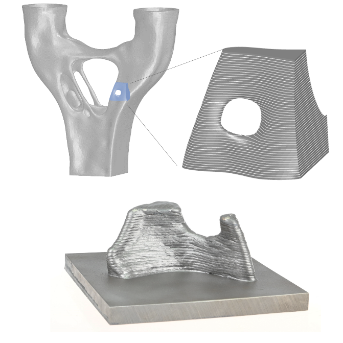
Fig 1: Part of a force flow optimized steel node for the investigation of geometrical features / Credit: A07/ J. Müller
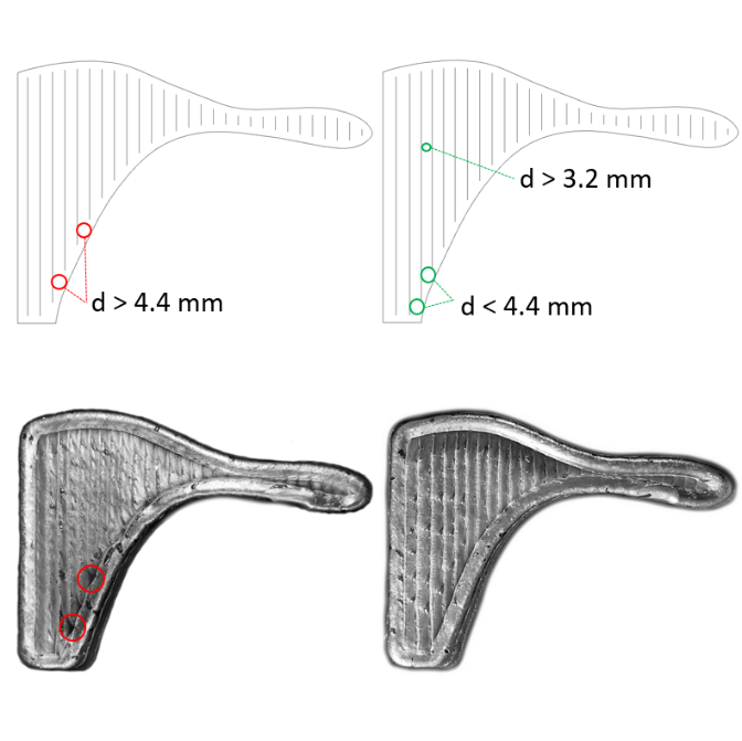
Fig 2: Adaption of the tolerance range for the bead distance in the path planning for solid parts, left: automatic path generation; right: modified robot path / Credit: A07/ J. Müller