Research Summary Report of C05
Jointing Principles for Combination of Concrete Elements Produced by Different Additive Manufacturing Processes
[14.11.2024]
Prof. Dr.-Ing. Harald Kloft Project leader, h.kloft@tu-braunschweig.de
Dr.-Ing. Abtin Baghdadi Researcher, a.baghdadi@tu-braunschweig.de
Dipl.-Ing. Lukas Ledderose Researcher, l.ledderose@tu-braunschweig.de
TU Braunschweig, Institute of Structural Design (ITE)
Prof. Dr.-Ing. Martin Empelmann Project leader, m.empelmann@ibmb.tu-braunschweig.de
TU Braunschweig, Institute of Building Materials, Concrete Construction and Fire Safety (iBMB)
In the second phase of the C05 project, research will focus on advancing connection methods and robotic manufacturing techniques, such as waterjet cutting and stamping in green-state concrete, while incorporating post-tensioning and steel connectors for higher load-bearing capacity and easier assemblage of AM concrete segments. The project will explore new design and construction strategies, such as the robotic “pick and place” method, while also improving subtractive post-processing techniques. Additionally, performance tests will evaluate enhanced joints and post-tensioned elements, with findings applied to optimize joint designs for larger-scale applications. A new method for result interpretation or calculation will be proposed for each joint and approach, including standard calculations and machine learning approaches. Therefore, the studied joints can be practically calculated and used for various dimensions, load combinations, and geometries.
Summary
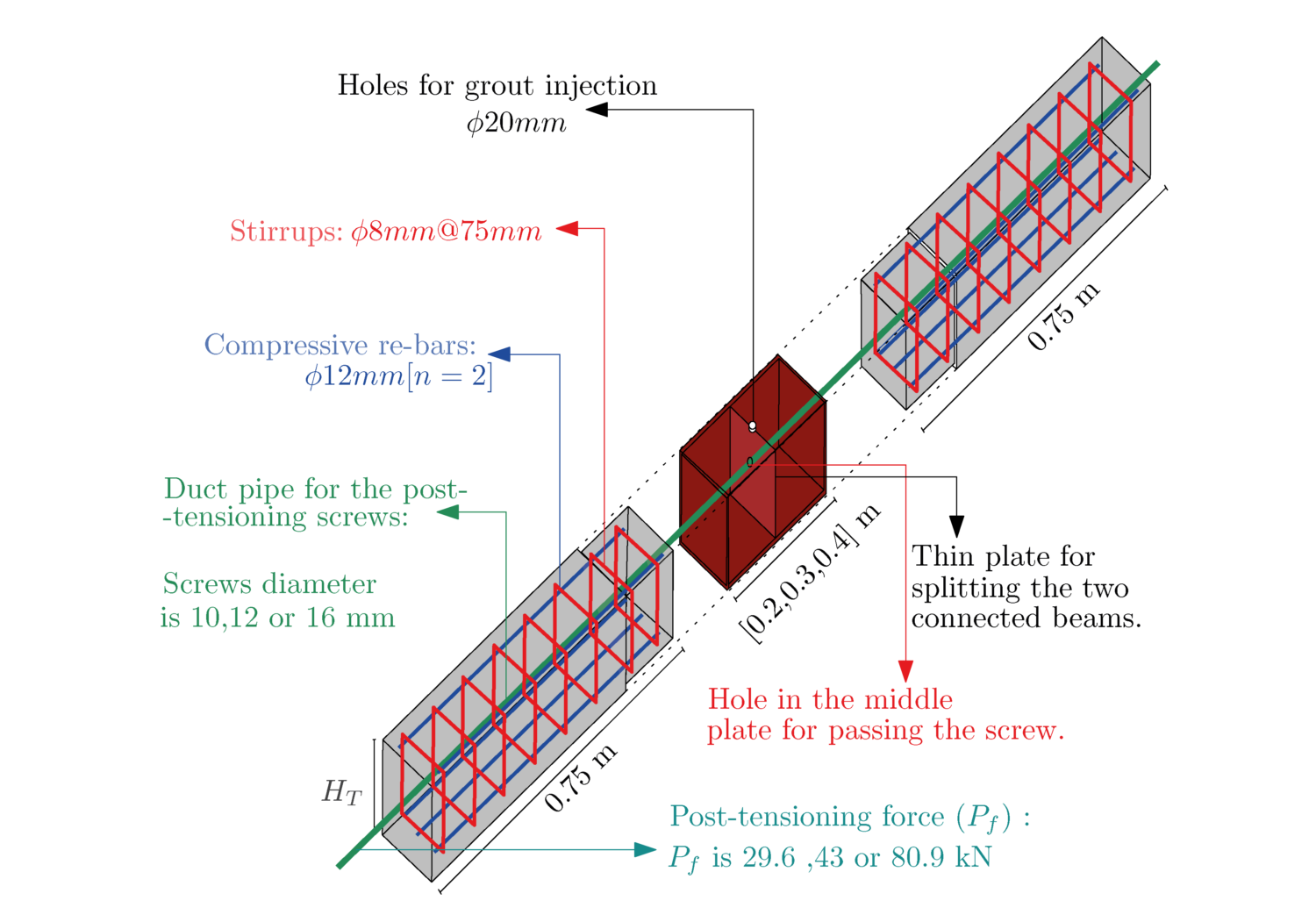
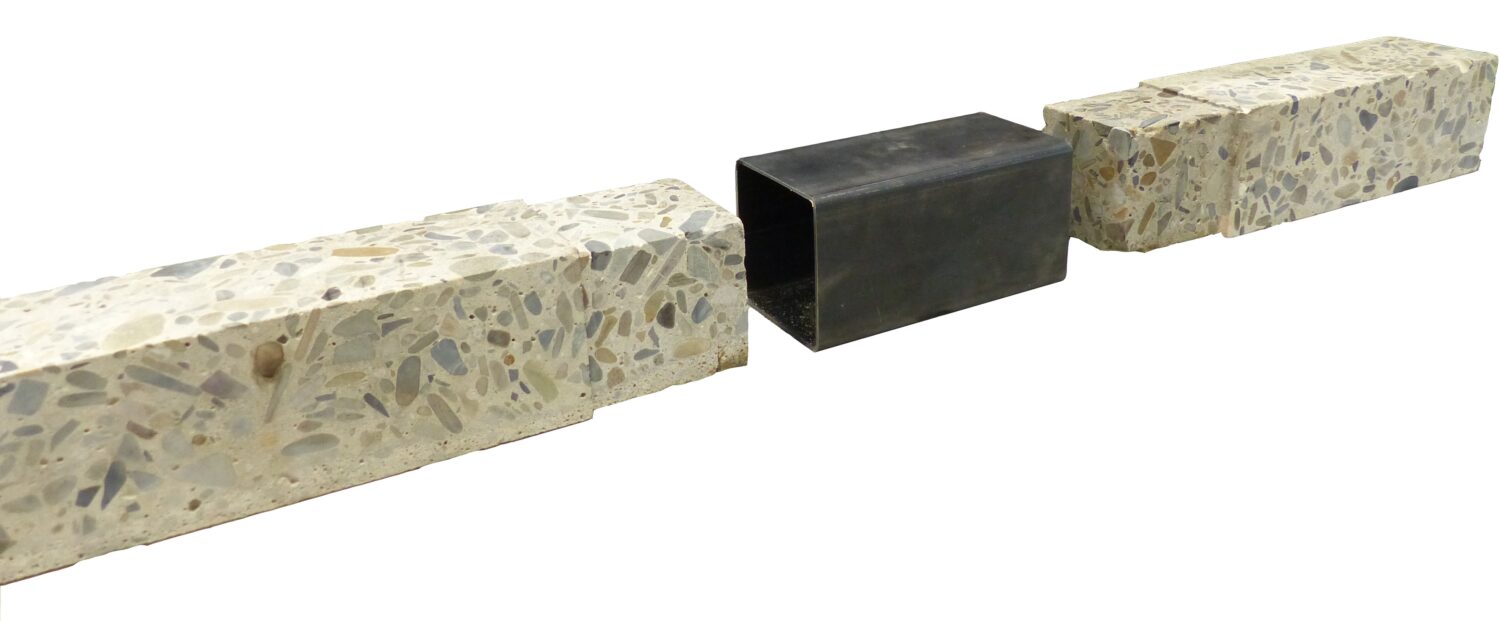
Post-tensioned square steel tube connectors for linear-shaped concrete elements. This research draws inspiration from Concrete-Filled Steel Tube (CFST) elements to develop and assess using simple steel tubes as joints for precast linear elements. The study introduces and evaluates straightforward joints where two precast reinforced concrete beams are housed within the tube (CFSTC). Combined with post-tensioning forces, the encasement of the beams within the tube creates strong integrity between the beams, akin to a head-to-head joint. Through 48 experimental tests, various connection parameters were systematically analyzed, such as the height of the beam and tube cross-section, the amount of re-bar, tube thickness, and length. The experimental framework used a three-point bending-shear testing method, and the results were compared to monolithic benchmarks. The findings reveal that these adaptable and ductile connections quickly achieve capacities comparable to monolithic beams. All parameters investigated impacted the connection’s capacity; however, the most significant factor was the tube length. Within the examined range, the tube length should equal twice the beam’s height to achieve the entire capacity of the concrete elements (performing like monolithic elements). Failure to adhere to this would hinder fully realizing the intended failure mechanism. As shown in Figure 1, the general geometry and the parameters for the CFSTC were carefully selected to analyze the connection strength and capacity effectively.
Current state of research
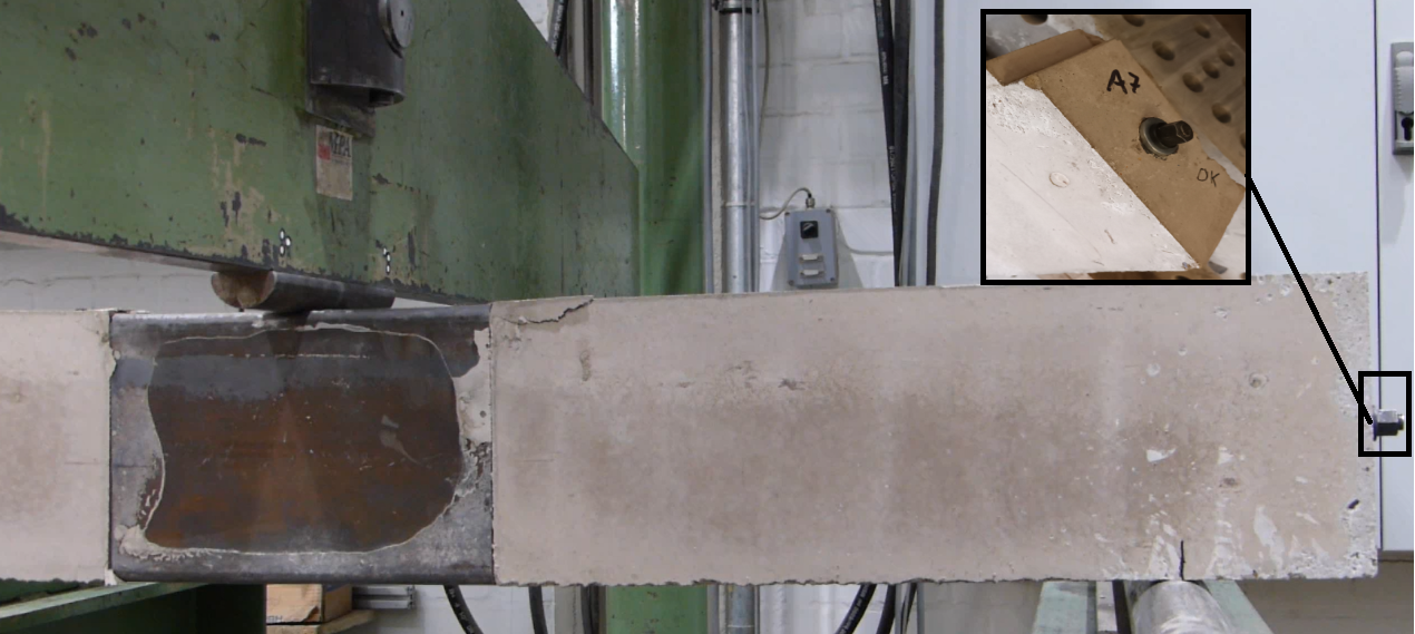
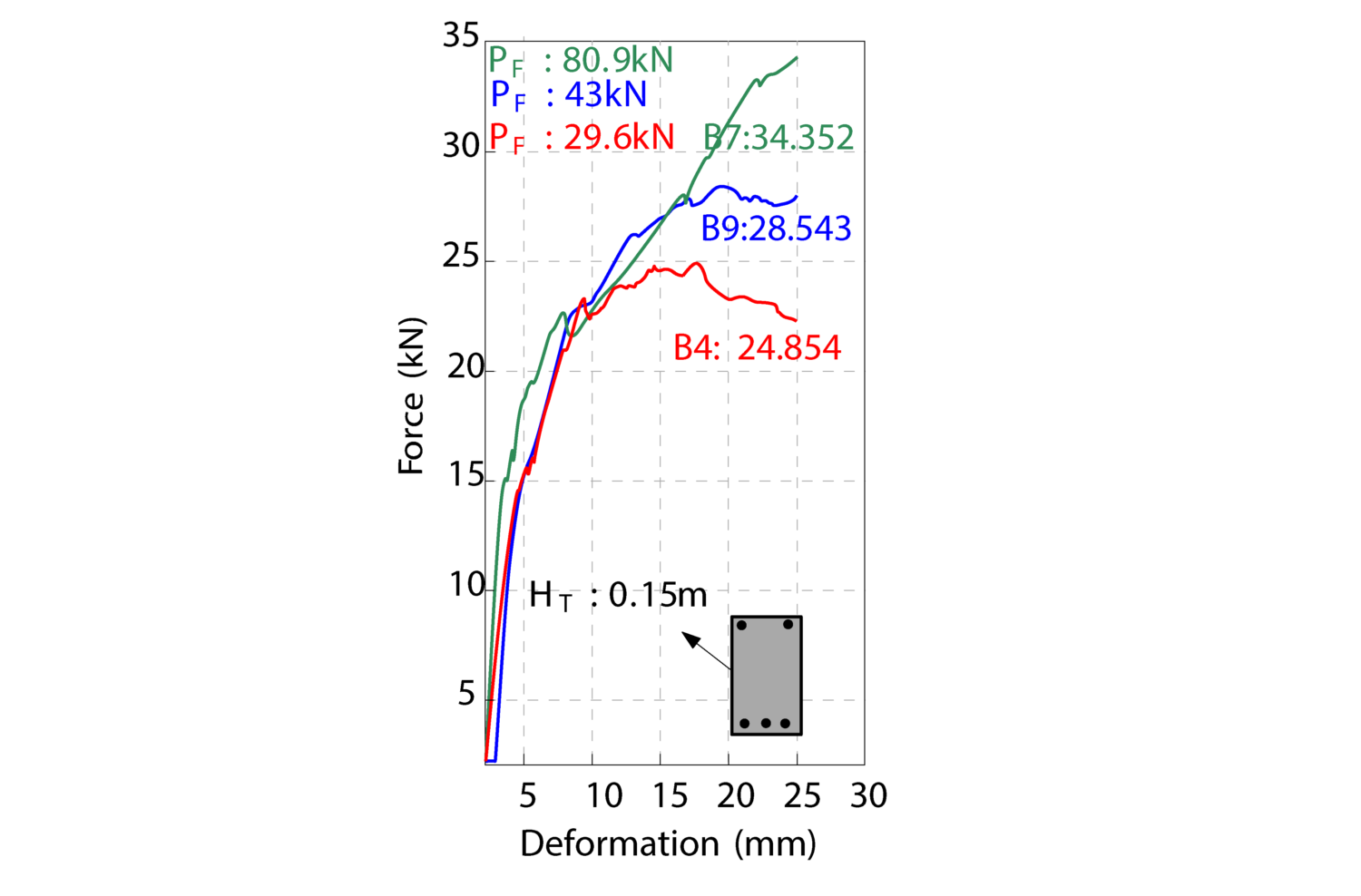
A total of 48 parametric beam elements were fabricated and tested to comprehensively evaluate the joints. Steel tube parameters included lengths of 20, 30, or 40 cm, heights of 10, 15, or 20 cm, and wall thicknesses of 4, 6, or 8 mm. For the concrete beam cross-section, variations were made in height and the number of longitudinal re-bars (2, 3, or 4, using 12 mm diameter bars). Different post-tensioning forces (29.6, 43, or 80.9 kN) were applied via various screw sizes that passed through embedded tubes to exert force at the beam ends during post-tensioning. All beams maintained a fixed width of 0.1 m. The beam samples were categorized into three groups: Group A consisted of 29 beam tests that focused on varying height, re-bars, and length while keeping the post-tensioning force constant at 43 kN. Group B included 15 elements that examined height and post-tensioning force, assessing the assembly process and its effect on capacity through a two-step production method. Group C, comprising four elements, acted as the control group, containing a monolithic beam, a post-tensioned beam without a tube, a tube without post-tensioning, and a pure steel tube. The three-point bending experimental setup, as illustrated in Figure 2, provided valuable data regarding the bending and shear behavior of the joints.
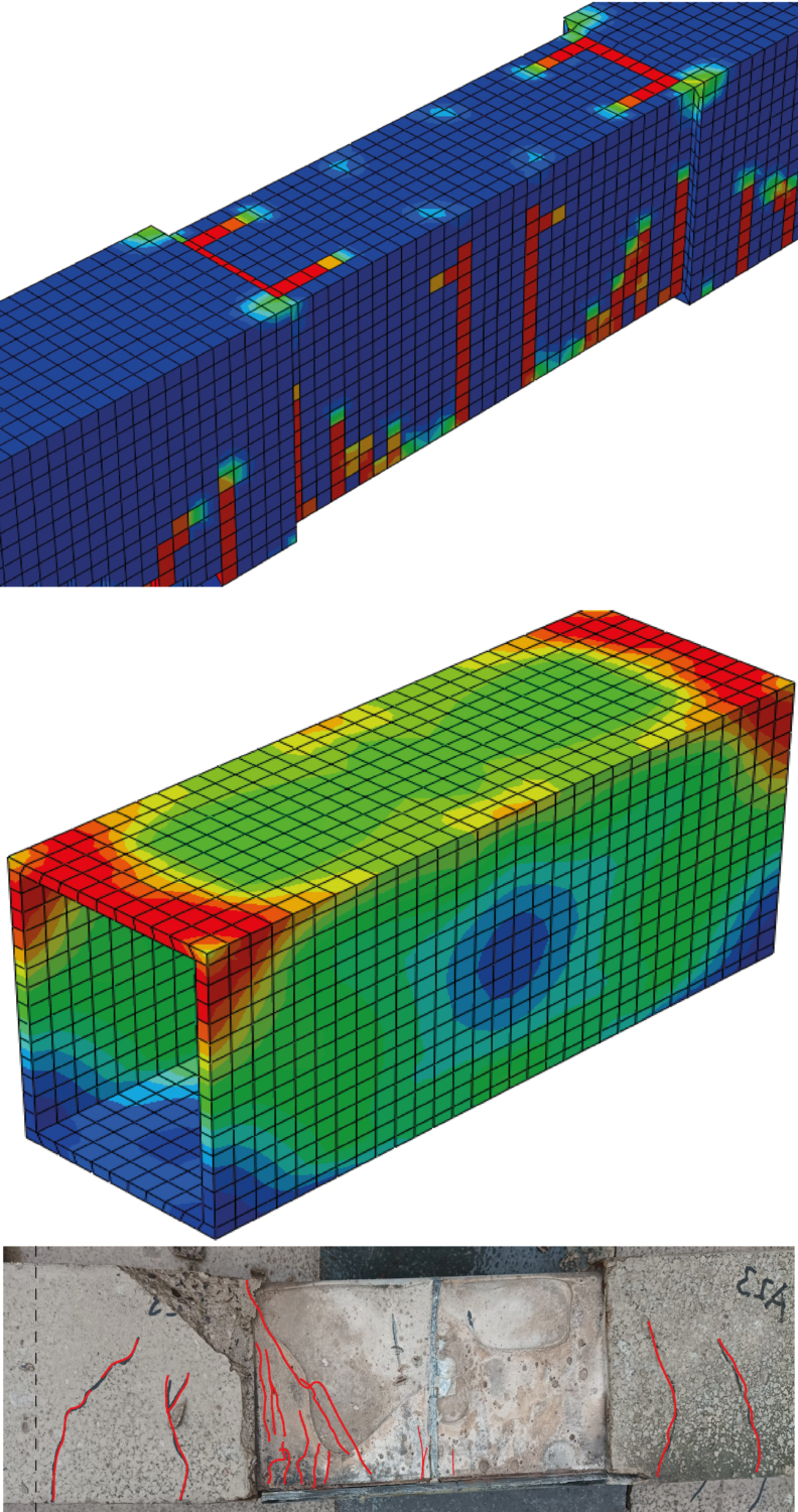
Finite element simulations of the connections were carried out using Abaqus-CAE-2019. The material properties of the concrete were derived from experimental tests and established standards, which included both compressive and tensile behaviors in addition to damage models based on the Concrete Damaged Plasticity framework in Abaqus. Similarly, the steel properties for both the re-bars and tubes were defined using calculated values for the modulus of elasticity and the nonlinear isotropic strain-stress relationship, informed by the properties of the purchased steel. This approach facilitated a precise simulation of the mechanical behavior of the beam elements and their joints. Figure 3 shows the results of validated finite element (FE) simulations and the corresponding failure cracks, demonstrating the accuracy of the FE models in predicting structural behavior under testing forces.
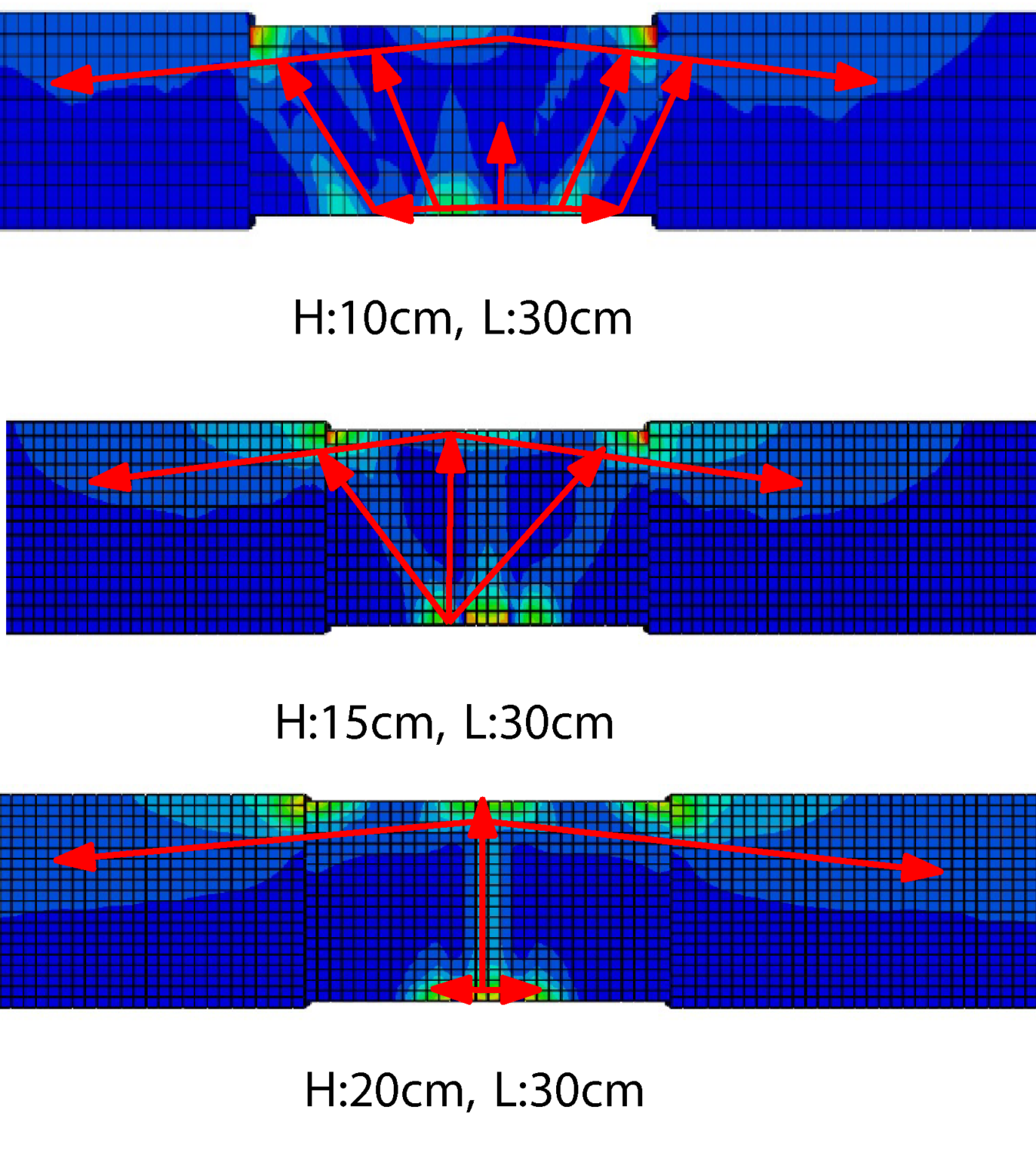
Tests comparing a monolithic reference beam with standard ACI calculations for CFSTC-jointed elements showed similar force-carrying capacities. Simulations and experiments identified three phases of failure during load application. Reducing tube height relative to its length increased capacity, while high post-tensioning forces prevented early failure. Tube wall thickness had minimal impact, but more re-bars improved tensile activation and bending force transmission. With simultaneous casting, Group A showed fewer imperfections, while Group B, with grout-filled gaps, had lower capacities due to shorter tubes. Tube length was the critical factor for optimal stress distribution. CFSTC elements can transfer forces in six degrees of freedom. The impact of varying beam heights on stress distribution and failure modes is depicted in Figure 4, and the influence of post-tensioning forces on the beam’s capacity is illustrated in Figure 5.
Subtractive Construction Technique:
Subtractive manufacturing has two methods for locating steel tubes: robotic sawing and milling. Sawing is quicker for straightforward shapes but may be influenced by vibrations. In contrast, milling enhances accuracy but also raises costs and production time. Precision is crucial for joint capacity, particularly when a gap exists between the concrete sides. Accurate milling elevates friction between steel and concrete. Potential solutions include using press fits or creating a larger gap for adhesive or mortar injection. Figure 6 showcases the robotic preparation used for attaching the three types of joints during the subtractive construction process.
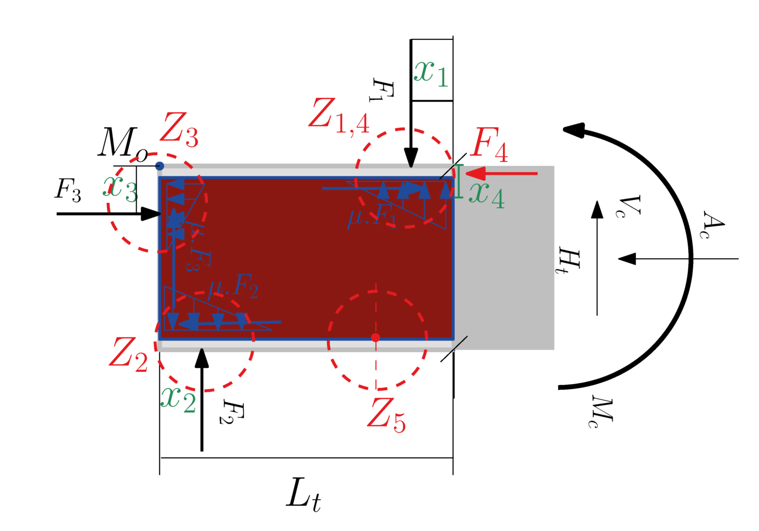
The first approach involves step-by-step calculations to analyze the forces and capacities of different steel tube or concrete section parts under bending and shear, aiming to establish a standard calculation approach. Despite its complexity, the standard calculation approach has proven to be accurate in solving examples similar to experimental tests. After evaluating initial internal forces, the proposed standard calculation method requires eight specific control inputs. Comparing these inputs with experimental test results further validates the effectiveness and safety of this approach for connection design. The details of the performances of these connections and their calculations method in details were published, recently [1,2]. Figure 7 shows the basic for calculated internal forces and probable failure modes for the proposed calculation method.
Evaluation of ML Capacity for Parametric Design of the Joints:
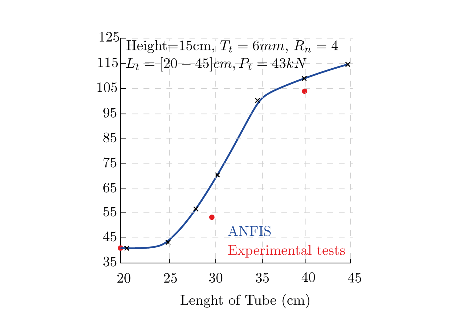
The second approach utilizes a look-up table created from experimental data, developing an Adaptive Neuro-Fuzzy Inference System (ANFIS) for data interpretation. ANFIS not only aids in assessing the capacity of elements that have not been experimentally tested but also mimics the calculation process. An evaluation of ANFIS’s performance against the original results highlights its impressive ability to analyze experimental data. With a maximum calculation error of only 13% when compared to the experimental tests, ANFIS demonstrates significant accuracy and ease of use. Figure 8 compares the ANFIS performance with the experimental test results.

