Research Summary Report of B04
Process Control and Adaptive Path Planning for Additive Manufacturing Processes Based on Industrial Robots with an Extended Degree of Freedom
[14.04.2023]
Lachmayer, Lukas; Doctoral researcher, lachmayer@match.uni-hannover.de,
Leibniz Universität Hannover, Institute of Assembly Technology (match)
Main goal
The main objective of project B04 is to achieve repeatability in concrete-based robot-guided additive manufacturing processes, which is crucial for enhancing productivity, sustainability and safety in the construction industry. While additive manufacturing processes offer several benefits such as reduced workload, decreased material usage, and minimized manual labor, the time- and environment-dependent material properties of fresh concrete can lead to unpredictable outcomes and component collapses. By achieving stability and accuracy in these processes, we can ensure consistent and predictable results, thereby increasing minimizing the risk of failures.
Summary
During the first funding phase, project B04 developed a path planning approach for producing large-scale concrete structures using additive manufacturing. The approach relies on a CAD file, sample wise shown in Fig. 1. The dark gray geometry represents the latest demonstrator produced in close cooperation with A04. In the first step of the path planning approach, an initial print path is generated using 2.5D slicing. Following this, the nozzle orientation is calculated to enable 3D production.
As shown in Fig. 1, the production system for project A04 expands the robot’s workspace by adding an additional 3-axis portal. Within the path planning environment, we resolve this redundancy using inverse differential kinematics.
After obtaining the initial path, we use the FEM environment developed by WG Hürkamp to calculate component stability during the printing process. In an optimization loop, we add the minimum required interlayer waiting times to prevent component collapse. This optimization loop is based on the simulated deformation of the component. Whenever the simulated deformation exceeds an empirical reference value, wait times are added.
During the production B04’s online control system is used to stabilize the printing process of project A04. The system was previously tested on simple wall segments and has now been adapted to work during the production of the reinforced demonstrator wall in Fig. 1. As shown in Fig. 2 (top) the system is informed about the planned layer width (Lw), nozzle distance (Ndist) and scanner orientation at each path point.
The control unit continuously acquires information about the printed object, generating a point cloud of the as-printed component useful for geometry evaluation. As shown in Fig. 3, the achieved deviation between as-planned and as-printed wall width is, in average, about 1 cm. This amount of additional material is necessary to allow green state milling and surface finishing within A04’s post processing.
current state of research
Within our current state of research B04 focuses on transferring the gained process control and path planning knowledge towards printing with mobile production systems. Our main focus is to allow mobile robots systems to print while driving.
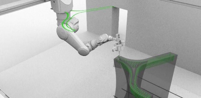
Fig 1: Visualized path planning for production of the demonstrator wall of project A04. Path planning incorporates the strand geometry model, optimized interlayer wait times, production and control parameters, as-well-as rotation angles for the process control unit / Credit: match, ITE
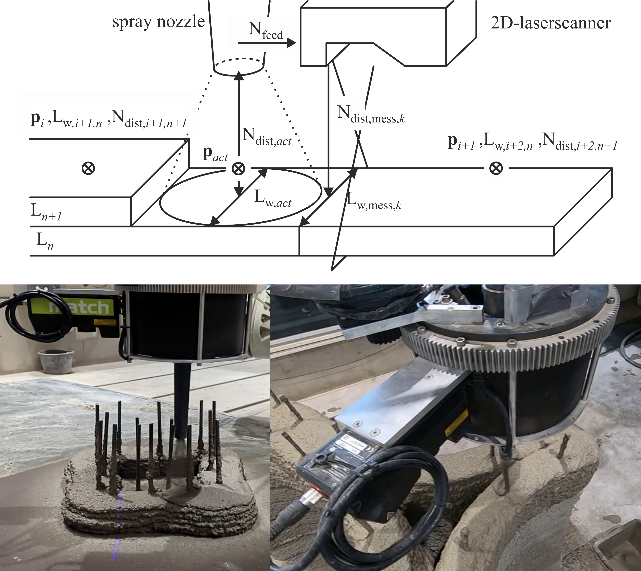
Fig 2: (top) Each path point pi contains information about the planned layer width Lw and the desired spray distance Ndist. A linear interpolation is used for continuous comparison with the measured values from the laser scanner Ndist,mess (bottom, left) Usage of control during production of a demonstrator column (bottom, right) Usage of the system during production of the demonstrator wall / Credit: match
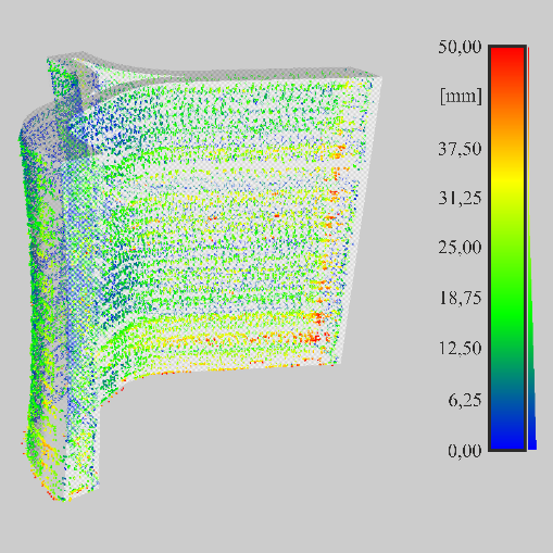
Fig 3: Width evaluation of the demonstrator wall based on the data collected during production. In cooperation with A04 a minimum amount of additional material in width is required for green state surface milling. / Credit: match
Usage of the online process control unit during the production of the demonstrator wall.