Research Summary Report of C04
Integrating Digital Design and Additive Manufacturing through BIM-Based Decision Support and Digital Twin Methods
[17.02.2023]
Borrmann, André, Project leader,andre.borrmann@tum.de,
Slepicka, Martin, Researcher,martin.slepicka@tum.de,
Technical University of Munich,Chair of Computational Modeling and Simulation
Summary
Computer Aided Manufacturing (CAM) methods, such as Additive Manufacturing (AM), are becoming increasingly popular in the construction industry since they offer more geometrical freedom than conventional methods. However, more complex data preparation is required for these methods and thus they have been considered separately from digital design so far. To increase the usefulness of AM for the industry, this project aims to integrate AM methods into the digital design methodology BIM. To achieve this, a framework is being implemented that acts as an intermediate layer between design and fabrication and includes methods to derive simulation models and to store and evaluate digital twin data (see Fig. 1), enabling a seamless integration of AM into the BIM workflow. When translating to FIM, all manufacturing information is stored in the BIM exchange data format IFC, exposing all intermediate steps, such as slicing and path planning. In the implemented data structure, the information is stored in a production-conscious manner, corresponding to the individual production steps required.
Current state of research
FIM enables seamless integration of AM into the BIM workflow by providing tools for two-way translation of geometric and semantic information (BIM) and manufacturing information (FIM). For the data storage of the FIM model, a data structure was developed based on the IFC format. To this end an IFC exporter was developed, that can export the fabrication information generated by the FIM framework to an IFC-file. At the same time a corresponding reader was developed that can interpret the exported data and directly translate it into robot movement. Depending on the utilized robot system, this reader can transform the stored path geometries into joint positions by calculating the inverse kinematics (IK) with the Denavit-Hartenberg (DH) parameters of the system. At the same time, it is now possible to compute a speed profile for the printing process based on the path geometry and the printer capabilities. The generated speed profile is designed to smoothen the printing process by minimizing any accelerations during the process by reducing the robot speed, e.g., when it is supposed to perform a sharp turn (see Fig. 2).
In a small-scale test setup, utilizing an UR10e industrial robot outfitted with a clay extrusion tool, the implemented tool makes use of the Real-Time Data Exchange (RTDE) interface of the UR robot and can communicate new robot positions in a high frequency (in the current implementation up to 125 Hz). This feature enables process adaptability by being able to make path and speed corrections during print time within a certain timeframe (lookahead time for IK-calculations). Thus, sensor data can be used for process optimization.
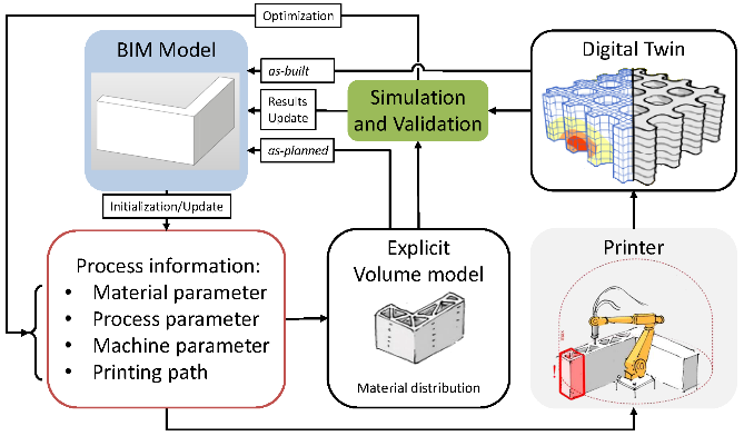
Fig. 1: FIM, linking digital design and fabrication as an inter-mediate layer via automated detailing and DT-methods.
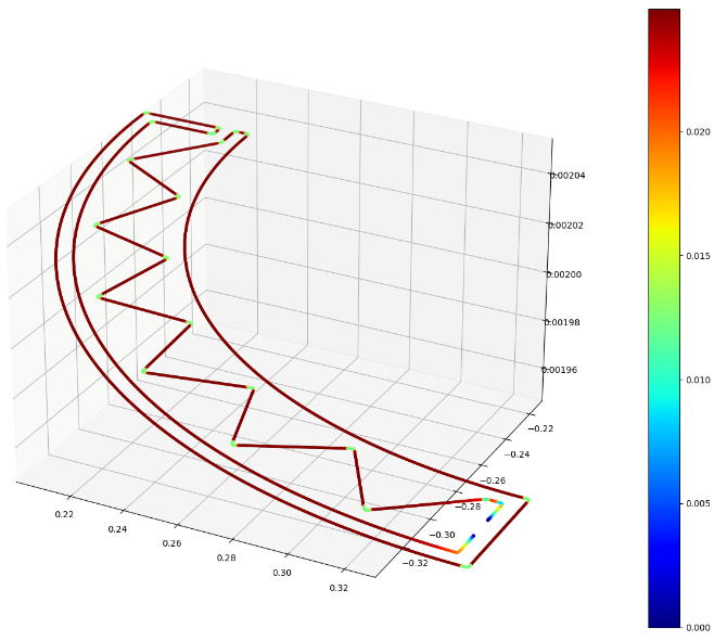
Fig. 2: Speed profile for one layer optimizing the acceleration values along the print path.
BIM to FIM: Workflow, data structure and application