Research Summary Report A07
Wire and Arc Additive Manufacturing (WAAM) of Complex Individualized Steel Components
[01.01.2021]
Müller, Christoph; doctoral researcher, christoph.mueller@tu–braunschweig.de,
TU Braunschweig , Institute for Structural Design (ITE)
This sub–project of the SFB 277 deals with the design process of components for additive manufacturing by Wire and Arc Additive Manufacturing (WAAM). In contrast to large industrial sectors such as mechanical engineering, aeronautical engineering or medical technology, components in the construction industry have to be designed under different general conditions.
If no building system is used to create a structure, the components are usually individual. These components are usually used in the building as a single part or in small quantities. With the implementation of additive manufacturing processes, these components are usually free–form geometries that result from the fulfilment of a wide range of boundary conditions. This includes improvements in material utilization through topology or shape optimization, geometries suitable for production and architectural design requirements.
Due to the frequently small number of identical components, the effort required to create the geometry must also be kept low, as otherwise the economic advantages of additive manufacturing are outweighed by the effort required in the design process.
The approach in this research project is to automate asmany work steps as possible. As a further guideline, the respective effort per work step should be kept as low as possible. Topology optimization serves as anexample here. Up to now, this has often been a decisive part of the design process. However, since geometry suitable for production is also required, time and resources can be saved by reducing the precision of topology optimization in favor of design speed.
For this purpose, a basic geometry is created that represents the design space. This geometry is transferred into a spatial framework and calculated by FEM for the corresponding load. Subsequently, the connection points are moved depending on the beam forces of the spatial beam system. In this process step, the points are considered as cellular automata and are all subject to the same set of rules.
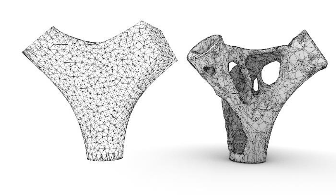
First geometry represents the design space and second geometry the outcome auf the implemented topology optimization with Grasshopper in Rhino. /Credit: ITE